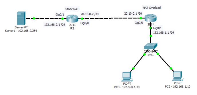
In the testing while ping from PC2 to Server1, i capture the packet that displayed below:
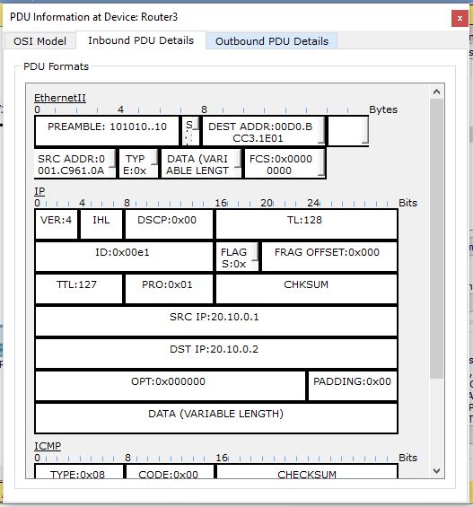
On the source table is not shows the PC2 ip address but swow the R1 ip interface (Nat outside) and same thing happen on server side. We already translate private address to public address so we can access server using ip address 20.10.0.2. To prove that i access web server from PC2 using ip address 20.10.0.2.
Accessing Web Server from PC2
The image above shows we successfully accessing web server from PC2.
VPN tunnels allow geographically separate private local area networks to be connected to each other across public wide area networks. In this way, a company or organization can have separate office networks virtually connected to each other across the public internet. Private local area networks connected by a tunnel across the internet have complete transparency to each other and are able to take advantage of all local area network resources as if they were locally available. In VPN Tunnels private networks are able to communicate across the public internet because all private network addressing and header information is not visible to public internet routers. The routers on the public internet do not have knowledge of the the private networks communicating across the internet. Unlike IPSec or OpenVPN tunnels, a GRE tunnel does not provide security or encryption by itself and therefore would not be a recommended method of creating a VPN tunnel across the internet if security or privacy is an important concern.
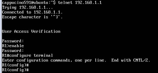
R1(config)#crypto key generate rsa
The name for the keys will be: R1.polar91.com
Choose the size of the key modulus in the range of 360 to 2048 for your
 General Purpose Keys. Choosing a key modulus greater than 512 may take
 a few minutes.

How many bits in the modulus [512]: 1024
% Generating 1024 bit RSA keys, keys will be non-exportable...[OK]

*Mar 1 0:2:42.596: %SSH-5-ENABLED: SSH 1.99 has been enabled
A firewall is a network security device that monitors incoming and outgoing network traffic and decides whether to allow or block specific traffic based on a defined set of security rules.
Firewalls have been a first line of defense in network security for over 25 years. They establish a barrier between secured and controlled internal networks that can be trusted and untrusted outside networks, such as the Internet.
A firewall can be hardware, software, or both.
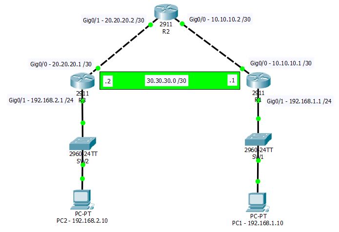
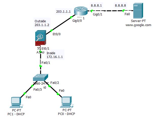
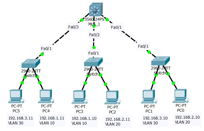
Topology
Configuration
Assign IP on Cisco ASA and ISP Router and set Interface Inside and Outside on Cisco ASA
ISP(config)#router ospf 1
ISP(config-router)#network 203.1.1.0 0.0.0.255 area 0
ISP(config-router)#network 8.8.8.0 0.0.0.255 area 0
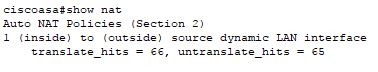
Create Object Network and Enable NAT
ciscoasa(config)#object network LAN
ciscoasa(config-network-object)#subnet 172.16.1.0 255.255.255.0
ciscoasa(config-network-object)#nat (inside,outside) dynamic interface
Create Access-list
ciscoasa(config)#access-list inside_to_internet extended permit tcp any any
ciscoasa(config)#access-list inside_to_internet extended permit icmp any any
ciscoasa(config)#access-group inside_to_internet in interface outside
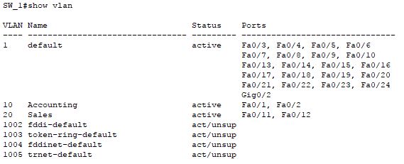
VLANs divide broadcast domains in a LAN environment. Whenever hosts in one VLAN need to communicate with hosts in another VLAN, the traffic must be routed between them. This is known as inter-VLAN routing. On Catalyst switches it is accomplished by the creation of Layer 3 interfaces (switch virtual interfaces (SVIs) ).
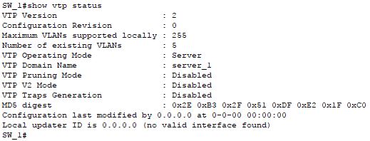
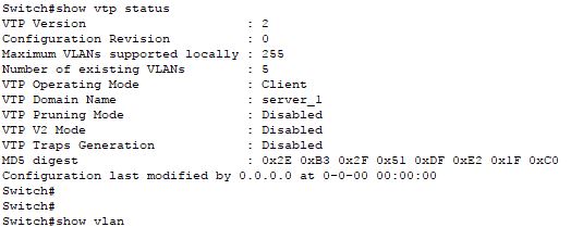
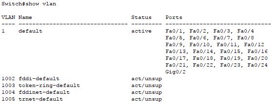
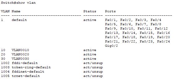
VLAN Trunk Protocol (VTP) reduces administration in a switched network. When you configure a new VLAN on one VTP server, the VLAN is distributed through all switches in the domain. This reduces the need to configure the same VLAN everywhere. VTP is a Cisco-proprietary protocol that is available on most of the Cisco Catalyst series products.
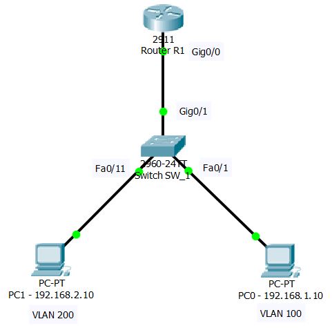
Routing on Stick (Inter VLAN Routing) used when we want to make connection between two hosts on different VLAN.
VLANs divide broadcast domains in a LAN environment. Whenever hosts in one VLAN need to communicate with hosts in another VLAN, the traffic must be routed between them. This is known as inter-VLAN routing.
A VLAN is a group of devices on one or more LANs that are configured to communicate as if they were attached to the same wire, when in fact they are located on a number of different LAN segments. Because VLANs are based on logical instead of physical connections, they are extremely flexible.
VLANs define broadcast domains in a Layer 2 network. A broadcast domain is the set of all devices that will receive broadcast frames originating from any device within the set. Broadcast domains are typically bounded by routers because routers do not forward broadcast frames. Layer 2 switches create broadcast domains based on the configuration of the switch. Switches are multiport bridges that allow you to create multiple broadcast domains. Each broadcast domain is like a distinct virtual bridge within a switch.
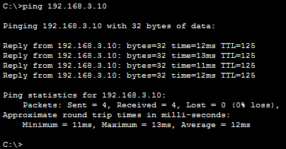
In this testing we will ping doing as follow to prove that VLAN configuration is working:
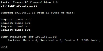
Ping from PC on the same Switch but different VLAN (example: PC0 ping PC12). On the working VLAN PC0 should not can ping PC12 although both PC IP address on the same subnet, because those PC virtually located on the dirrefent LAN.
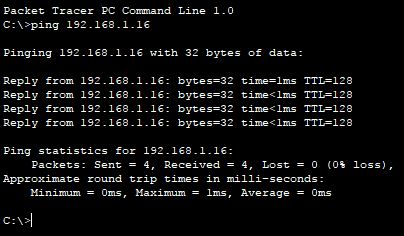
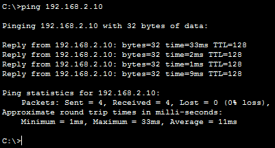
Ping from PC on the same LAN but different Switch (example: PC12 ping PC14). PC12 should be can ping PC14 because both PC located on the same VLAN.
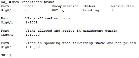
Note: to make this connection happen link between Switch SW_1 and SW_2 must be already configured as Trunk.
Static routing is a form of routing that occurs when a router uses a manually-configured routing entry, rather than information from a dynamic routing traffic. In many cases, static routes are manually configured by a network administrator by adding in entries into a routing table, though this may not always be the case. Unlike dynamic routing, static routes are fixed and do not change if the network is changed or reconfigured. Static routing and dynamic routing are not mutually exclusive. Both dynamic routing and static routing are usually used on a router to maximise routing efficiency and to provide backups in the event that dynamic routing information fails to be exchanged. Static routing can also be used in stub networks, or to provide a gateway of last resort.